220-1100 nm UV-Silicon 2 W Divergent Beam 1 inch ID Integrating Sphere
220-1100 nm UV-Silicon 2 W Divergent Beam 1 inch ID Integrating Sphere
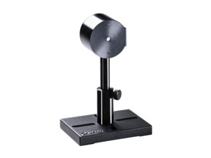
The IS-1-2W calibrated integrating sphere photodiode laser measurement sensor has a 1 inch internal diameter. It is used for measuring divergent beams up to +/-50 degrees, especially from fibers. It has a 5 mm aperture and can measure optical power from 500 nW to 2 W. It covers the spectral range from 220 to 1100 nm.
- 1.0 inch ID integrating sphere for divergent beam
- UV-Silicon photodiode for 220 to 1100 nm spectral range
- 500 nW to 2 W power measurement range
- 5 mm diameter aperture See All Features
Specifications
- Product NameIS-1-2W
- TypeDivergent Beam
- Sphere Size1.0 inch ID
- Aperture SizeØ5 mm
- Detector TypeUV-Silicon
- Spectral Range220-1100 nm
- Minimum Power500 nW
- Maximum Average Power2 W
- Maximum Pulse Energy600 µJ
- Maximum Average Power Density1 kW/cm²
- Response Time0.2 s
- Beam Size Sensitivity±2 %
- Maximum Beam Divergence±50 deg
- DimensionsØ50 x 38 mm
- Cable Length1.5 m
- CE ComplianceYes
- UKCA ComplianceYes
- China RoHS ComplianceYes
Features
Integrating Spheres for Divergent Light Sources
Integrating spheres are used when we have divergent light sources. An integrating sphere has its inner surface coated with a surface that highly reflects (typically 99%) in a scattering, nonspecular way. Thus when a divergent beam hits the walls of the integrating sphere, the light is reflected and scattered many times until the light hitting any place on the walls of the sphere has the same intensity.
A detector placed in the sphere thus gets the same intensity as anywhere else and the power the detector detects is thus proportional to the total incident power independent of the beam divergence. (The detector is so arranged that it only sees scattered light and not the incident beam). An ideal integrating sphere has a surface with reflective properties that are Lambertian. This means that light incident on the surface is scattered uniformly in all directions in the 2pi steradians solid angle above the surface. The surface used by Ophir closely approximates a Lambertian surface.
Measuring Beams Coming Out of A Fiber
When you need to measure a beam coming out of a fiber, there are some parameters that might have a somewhat different meaning than they do when referring to "regular" beam measurements. Missing some of these points could lead to incorrect measurement, and possible equipment damage. This video clarifies some issues you'll need to keep in mind so you can set up -- and perform -- this measurement correctly.
Measuring Power of LEDs: UV, Visible and NIR
Measuring the emitted power of an LED can be tricky. It is different in some important ways from measuring the power of a laser beam. This video shows you how to use the Ophir 3A-IS Integrating Sphere Sensor, along with the Auxiliary LED accessory, to easily make accurate measurements in LED applications.
Calibration Factors - Laser Power/Energy Meter
When a power/energy meter is in "Calibrate" mode, various "Factors" are displayed to the user. This video explains the meaning of each of these factors.
Frequently Asked Questions
- Integrating spheres are used when you have divergent light sources. How do they work?Answer
Integrating Sphere Theory
Integrating spheres are used when we have divergent light sources. As shown in the illustration, an integrating sphere has its inner surface coated with a surface that highly reflects (typically 99%) in a scattering, nonspecular way. Thus when a divergent beam hits the walls of the integrating sphere, the light is reflected and scattered many times until the light hitting any place on the walls of the sphere has the same intensity.A detector placed in the sphere thus gets the same intensity as anywhere else and the power the detector detects is thus proportional to the total incident power independent of the beam divergence. (The detector is so arranged that it only sees scattered light and not the incident beam). An ideal integrating sphere has a surface with reflective properties are Lambertian. This means that light incident on the surface is scattered uniformly in all directions in the 2pi steradians solid angle above the surface. The surface used by Ophir closely approximates a Lambertian surface.

Step 1 – Starting position3A-IS Series
The 3A-IS series has two 50mm integrating spheres in series with a photodiode detector. The two series spheres scramble up the light very well thus giving output very independent of incident beam divergence angle. The two spheres in series also insure that the light hitting the detector is greatly reduced in intensity thus allowing use up to 3 Watts even though photodiodes saturate at about 1mW. There are two models, the 3A-IS with a silicon photodiode for 400 – 1100nm and the 3A-ISIRG with an InGaAs detector for 800 – 1700nm
- Do I need to recalibrate my instrument? How often must it be recalibrated?Answer
Unless otherwise indicated, Ophir sensors and meters should be recalibrated within 18 months after initial purchase, and then once a year after that.
- How much variation in water temperature or flow rate is allowed in Ophir water cooled sensors?Answer
Ophir water cooled sensors measure the heat flow across the thermopile disc and therefore are quite insensitive to the water temperature or flow rate within the given specified limits. However, sudden changes in the water temperature or water flow rate can cause a disturbance to the reading until the flow rate/temperature stabilizes again. Therefore we specify in our water cooled sensors that the water temperature should not change faster than 1 °C/min. Likewise, sudden changes in flow rate (e.g. switching another device connected to the same water line on and off) can results in temporary disturbances in the power reading.
- When using the fiber optic adaptor, how do we handle power loss due to the fiber relative to calibration?Answer
All Ophir power meters, including photodiode power meters, have an air gap between the fiber tip and the sensor. Therefore they measure the power emitted by the fiber into the air and do not take into account any reflection losses there are in the fiber. Therefore, if in actual use, the fiber will be coupled with no loss to another element, then the losses should be added to the reading. These losses are usually about 4%. Thus if the reading on the Ophir meter is say 100 mW, then in lossless use, the real power will be 104 mW.
- The damage thresholds for your Integrating Sphere sensors are only given for the sphere surface – what about for the detector?Answer
The damage threshold is given in the datasheet for the sphere inner surface rather than for the detector itself, because the sphere surface will reach its damage threshold long before the detector will. A beam entering the sphere will first hit the inner surface on the opposite side of the sphere, and if at that point the power density is too high it will damage the inner surface of the sphere. From that first "meeting" of the beam with the white diffuse reflective inner sphere surface, it will be diffusely reflected multiple times. Since there is no direct line of sight between the entrance port and the detector, any light reaching the detector has already been uniformly distributed around the inner surface of the sphere, but light in that "first impact" on the sphere wall has not yet been uniformly distributed. Therefore, the "damage threshold" for the device is the maximum power density of the beam as it first hits the inner wall.
- Among the Integrating Sphere accessories offered, there are “Port Plugs” (white), and “Port Covers” (black). What’s the difference?Answer
An unused port should be closed, to prevent unwanted light from entering the sphere. Closing it with a diffuse white port plug, however, adds the surface area of that plug to the (diffuse white) effective area of the sphere that is doing the “integrating”. For a calibrated integrating sphere sensor, this change in the behavior of the sphere changes its calibration, and results in incorrect readings. In such applications, a black “Port Cover” should be used.
- There are several models of IS6 integrating sphere detectors. how can I select the right one?Answer
There is a simple to use selection guide.
- Are there any special problems with the calibration stability of integrating sphere sensors?Answer
The Ophir integrating sphere sensors, models 3A-IS and 3A-IS-IRG have a white diffuse reflecting coating on the inside of the integrating sphere. The sensitivity of the sensor is quite sensitive to the reflectivity of the coating. If the coating absorption goes up 1%, it can cause a 5% change in reading. Therefore, care must be taken not to soil or damage the white coating of the sensors. Also it may be a good idea to send the sensors for recalibration yearly.
Accessories
Fiber Connector Adapters
These adapters allow for power measurement of connectorized fiber-optic cables. The sensor may need an additional mounting bracket to connect to these fiber adapters.
| Compare | Description | Drawings, CAD & Specs | Avail. | Price | ||
|---|---|---|---|---|---|---|
 | 7Z08227SC Fiber Connector Adapter, Power and Energy Sensors | |||||
 | 7Z08226ST Fiber Connector Adapter, Power and Energy Sensors | |||||
 | 7Z08229FC Fiber Connector Adapter, Power and Energy Sensors | |||||
 | 1G01236ASMA Fiber Connector Adapter, Power and Energy Sensors |
Fiber Adapter Mounting Bracket
Fiber adapter mounting bracket (fits all types above)
| Compare | Description | Drawings, CAD & Specs | Avail. | Price | ||
|---|---|---|---|---|---|---|
 | 7Z08331Fiber Adapter Mounting Bracket, IS-1-2W Integrating Sphere Sensors |
Extended Warranty for Sensor
Customers that purchase the above items also consider the following items. Ophir-Spiricon meters and sensors include a standard manufacturers warranty for one year. Add a one year Extended Warranty to your meter or sensor, which includes one recalibration.
| Compare | Description | Drawings, CAD & Specs | Avail. | Price | ||
|---|---|---|---|---|---|---|
 | XWAR-SENSORExtended Warranty for Sensor |
Resources
Data Sheets
Integrating Spheres Small Dimensions 1”-1.6” Datasheet(171.1 kB, PDF)
Catalogs
Power Sensors Catalog(11.2 MB, PDF) Laser Power & Energy Measurement and Laser Beam Analysis Catalog(27.5 MB, PDF)
Drawings & CAD
IS-1-2W Drawing(122.3 kB, PDF)
Tutorials
Technical Notes
5 Situations Where Laser Performance Measurement is Necessary How do I know what range, or scale, to set my power/energy meter to? Measuring Average Power of Pulsed Lasers with Photodiodes(114.5 kB, PDF) Fighting Viruses with UV-C LED Light Measuring Power of Divergent Beams with Integrating Sphere Sensors